PrimaX IR+ Calibration
The device can be calibrated using either the optional calibration cap locally at the sensor, or using the HART digital interface.
NOTE: MSA recommends using a calibration gas value in the middle of the measuring range for optimum calibration.
Calibration Methods
WARNING!
The standard environmental guard is designed to offer fast response time and must not be used for bump or calibration without the Remote Calibration Inserts (see chapter Ordering Information, P/N 10122783). Failure to do so could dilute the sample and result in inaccurate calibration.
Failure to follow this warning can result in serious personal injury or death.
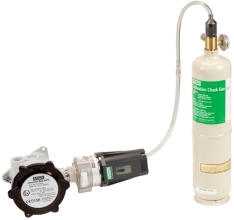
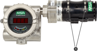
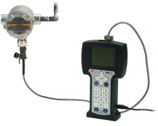
Figure 12 Remote HART Calibration Kit

Although both a full calibration (zero and span) and zero only calibration can be performed on the device, a zero only calibration may be sufficient to properly calibrate the monitor. Normally, any degradation of the sensor's performance is associated with slight drifts in zero that, in turn, will adversely affect its span performance. After completing the zero calibration, perform a span check to ensure proper operation. For a span check, apply a gas of known concentration and verify that the measured response is within acceptable limits. If the span check is unsuccessful, perform a full zero and span calibration.
Alternate Span Gas Settings
To achieve the most accurate calibration it is always best to use the gas of interest and calibrate at the operating temperature. If the target span gas is not available, an alternative span gas can be used with the values show in the table below. The sensor label will identify the span gas and value used by the factory for calibration. Use of a reference gas for calibration may decrease accuracy. The user may change the gas monitor's span value, gas name and gas curve through use of the PrimaX IR+ Link software found on https://msasafety.info/PrimaXIRPlus. Please refer to the PrimaX IR HART Specification and the PrimaX IR+ Link Help Guide on https://msasafety.info/PrimaXIRPlus.
| Target Gas | 100% LEL1 |
Performance Approved Range |
Measuring Range | Calibration Gas | Span Value2 | t50 | t90 |
Gas Cal Curve No. |
|---|---|---|---|---|---|---|---|---|
| Methane | 4.40% | 0-100% | 0-100% | 2.5% v/v Methane | 57% | ≤ 7 s | ≤ 15 s | 1 |
| Methane | 5.00% | 0-100% | 0-100% | 2.5% v/v Methane | 50% | ≤ 7 s | ≤ 15 s | 1 |
| Propane | 1.70% | 0-100% | 0-100% | 0.6% v/v Propane | 35% | ≤ 7 s | ≤ 15 s | 2 |
| Propane | 2.10% | 0-100% | 0-100% | 0.6% v/v Propane | 29% | ≤ 7 s | ≤ 15 s | 2 |
| Toluene | 1.00% | 0-30% | 0-100% | 2.5% v/v Methane | 57% | ≤ 11 s | ≤ 28 s | 3 |
| Toluene | 1.10% | 0-30% | 0-100% | 2.5% v/v Methane | 52% | ≤ 11 s | ≤ 28 s | 3 |
| n-Butane | 1.40% | 0-30% | 0-100% | 0.6% v/v Propane | 37% | ≤ 10 s | ≤ 24 s | 2 |
| n-Butane | 1.50% | 0-30% | 0-100% | 0.6% v/v Propane | 35% | ≤ 10 s | ≤ 24 s | 2 |
| Acetone | 2.50% | 0-100% | 0-100% | 2.5% v/v Methane | 44% | ≤ 11 s | ≤ 25 s | 2 |
| Propylene | 2.00% | 0-50% | 0-100% | 1.0%v/v Propylene | 50% | ≤ 11 s | ≤ 25 s | 3 |
| Propylene Oxide | 1.90% | 0-100% | 0-100% | 2.5% v/v Methane | 19% | ≤ 11 s | ≤ 25 s | 3 |
| Propylene Oxide | 2.30% | 0-100% | 0-100% | 2.5% v/v Methane | 16% | ≤ 11 s | ≤ 25 s | 3 |
| Ethane | 2.40% | 0-50% | 0-100% | 1.2%v/v Ethane | 50% | ≤ 11 s | ≤ 23 s | 3 |
| Ethylene | 2.30% | 0-100% | 0-100% | 1.35% v/v Ethylene | 59% | ≤ 10 s | ≤ 23 s | 3 |
| Ethylene | 2.70% | 0-100% | 0-100% | 1.35% v/v Ethylene | 57% | ≤ 10 s | ≤ 23 s | 3 |
| Cyclopentane | 1.40% | 0-100% | 0-100% | 0.6% v/v Propane | 35% | ≤ 10 s | ≤ 25 s | 2 |
| Cyclopentane | 1.50% | 0-100% | 0-100% | 0.6% v/v Propane | 33% | ≤ 10 s | ≤ 25 s | 2 |
| Isobutane | 1.30% | 0-70% | 0-100% | 0.65%v/v IsoButane | 50% |
≤ 12 s |
≤ 26 s |
2 |
| Isobutane | 1.80% | 0-70% | 0-100% | 0.6% v/v Propane | 39% |
≤ 12 s |
≤ 26 s |
2 |
| Ethyl Acetate | 2.00% | 0-100% | 0-100% | 2.5% v/v Methane | 21% |
≤ 12 s |
≤ 25 s |
2 |
| n-Hexane | 1.00% | 0-10% | 0-100% | 0.5%v/v n-Hexane | 50% | ≤ 11 s | ≤ 24 s | 2 |
| n-Pentane | 1.10% | 0-30% | 0-100% | 0.55%v/v n-Pentane | 50% | ≤ 11 s | ≤ 24 s | 2 |
1 IEC/UL/EN 80079-20-1 was used as bases for converting test and calibration gas concentrations from % LEL to % volume fraction
2 For the measurement of n-Pentane, n-Hexane, Propylene, Ethane or Isobutane PrimaX IR shall be calibrated with the target gas at a span value of approximately 50% LEL.
Calibration Cap Procedure
| 1. | Remove the environmental guard from the device. |
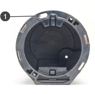
| 2. | The calibration cap is equipped with a slot for an optional tether retention system. The figure below shows the location of the tether slot. |
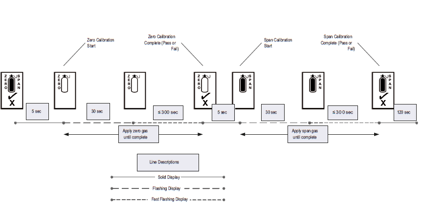
| 3. | If the user can confirm that the ambient air is free of combustible gas, ambient air can be used in place of the zero gas cylinder. For a visual representation of the calibration process see (→ Figure 17 ). |
| 4. | Install the calibration cap. Press firmly to ensure cap is properly seated. |
| ○ | The calibration process will start automatically when the cap is fully seated on the sensor housing. |
| ○ | Under normal conditions, the display will show all icons steady at power-up. |
| 5. | The calibration cap display indicates the zero gas cylinder symbol and flashes, indicating that the device is in Zero Calibration mode. |
| ○ | The initial 30 seconds is intended to give the user time to apply gas to the sensor. During this time, the user can abort the process by removing the calibration cap. |
| ○ | After the initial 30 seconds, the device will start the Zero calibration adjustment. The Zero Calibration is indicated by the white cylinder (→ Figure 15 ) and the word "Zero". |
| ○ | Removal of the calibration cap after the initial 30 seconds will result in a calibration fault. This will abort the present calibration and the device will continue to operate with the previous calibration settings. |
| 6. | Apply zero gas to the calibration port at an approximate flow rate of 1.5 LPM while the cylinder symbol is flashing. Zero gas can be supplied as ambient air or from the zero gas cylinder in the calibration kit (→ Calibration Kits). |
| 7. | When the Zero calibration is successful, the tick symbol “✓” will appear. If only performing a Zero calibration, remove the calibration cap. Following a successful zero, the span process will automatically begin within 30 seconds following the zero symbol “✓”. |
| 8. | If the Zero calibration fails, the display will show an X for approximately 2 minutes, and will then power down. |
| ○ | If the Zero calibration fails, remove the calibration cap and reinstall to start another zero attempt. If multiple failures occur, contact an authorized MSA service center. |
| 9. | When the display flashes the span gas symbol, apply the span gas through the calibration cap port (→ Figure 11 ). |
| ○ | The unit must see gas within 30 seconds after the span symbol starts to flash or a calibration fault may occur. The initial 30 seconds are intended to give the user time to apply gas to the sensor. During this time, the user can abort the Span process by removing the calibration cap. |
| ○ | The display will then flash at a faster rate to indicate active calibration by the sensor. |

| 10. | When the Span calibration is successful, the tick symbol “✓” will appear. If the Span calibration fails, an "X" will be displayed for approximately 2 minutes, and the device will then power down. |
| ○ | See chapter Maintenance for subsequent action upon calibration failure. |
| 11. | When calibration is complete, stop the gas flow and remove the calibration cap. Reconnect the environmental guard or flow cap to the sensor. The calibration cap will automatically power down once removed from the sensor. The 4 - 20 mA is held at the sensor calibration level for two minutes to reduce the chance of a nuisance alarm upon completion of a calibration procedure. |
| ○ | During calibration and this 2 minute period, the unit will not be detecting any gas in the ambient area. |
| • | Alternately, the device can be commanded via HART to track the gas level during calibration (see the Calibration Signal Enable/Disable command in the HART Specification). |
| ○ | Once the calibration cap is removed it can take up to two minutes for gas to diffuse and the device to read normal ambient levels. |
When a Zero or Span calibration failure occurs, the device reverts back to its previous successful calibration settings.
If the calibration cap is left on for more than 15 minutes after calibration concludes, the 4 to 20 mA signal indicates Fault status.
When the calibration cap battery is nearing the end of its useful life, the LCD will display all the icons in a series of rapid flashes at power-up before it starts the normal calibration cycle. The battery is non-serviceable and the calibration cap would need to be replaced once the battery is depleted.
WARNING!
The calibration cap must be removed from the device after completing the Zeroing and/or Spanning procedure. Failure to do so could restrict gas flow to the sensor and result in erroneously low readings.
Failure to follow this warning can result in serious personal injury or death.
HART Calibration Procedure
The device can be calibrated using a HART compatible communications interface with Device Description capability (DD), such as the Emerson 375 or 475 Field Communicator ( → Figure 13 ). Ensure that the HART hand-held communicator is compatible with the area classification. This hand-held HART communicator must be HART revision 7.0 compliant and can be obtained from a HART authorized supplier. See the PrimaX IR HART specifications document (10125187), which can be found on the product page https://msasafety.info/PrimaXIRPlus, for more information.
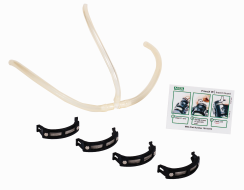
Calibration can also be performed via the HART interface with optional screen inserts in the Environmental Guard. The environmental guard can be fitted with these screens that will allow the calibration gas to be retained in the enclosure long enough for a valid zero and/or span reading to be obtained under still-air conditions (→Figure 18 ).
WARNING!
Use of the insect screens can increase the sensor response time to ambient gas conditions. Ensure that the conditions are appropriate for use of these screens.
Failure to follow this warning can result in serious personal injury or death.
When supplying tubing to the environmental guard to allow remote HART calibration, gas should be delivered to both ports of the environmental guard from a 1.5 l/min regulator (→ Figure 18 ):
When used under windy conditions, a calibration cover must be used instead of the environmental guard while applying the zero and span gas.
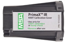
For a picture of the cover see Figure 19 .
WARNING!
Ensure that the calibration cover is removed after calibration is complete. This cover is intended to block the flow of ambient air into the sensor during calibration, and in normal operation must ALWAYS be removed.
Failure to follow this warning can result in serious personal injury or death.
For applications where access to the HART signal is needed in hazardous areas, MSA provides the HART junction box with intrinsically safe HART port (→ Figure 20 ).
The explosion-proof port allows access via a HART hand-held controller using the cable shown above (part number 10081441).